Some findings on DCX2496's LVDS modification; DCX2496のLVDS改造でわかったこと
I made up a test setup using ES9038q2m boards equipped with I2S input from Amazon to test DCX2496 LVDS modification. This board is cheap, not requiring MCLK, and level control is included, so it is ideal for test purpose. I found that the idea to use isolation transformers installed in RJ45 jack did not fit to isolate I2S signal. I am wondering if the transformers can handle LRCLK because the frequency is as low as 96KHz. That is why I choose LVDS receiver with hysteresis.
The result was different from I planned. The signal pass goes through:
- 1000 Base-T RJ-45 (0838-1X1T-W7) connector driven by ADN4667
- CAT6 cable
And
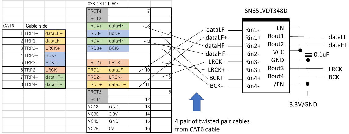
- another 1000 Base-T RJ-45 (0838-1X1T-W7) connector
- received by SN65LVDT348D LVDS receiver
The result is unsuccessful.
It is okay with audio signal, but if the audio level goes down, the test setup makes random buzzing sound. I could not identify the cause, so, I bought inexpensive oscilloscope (Hantek 6022BE) to see what is happening.
Looking at 4 pair of signals, the findings are:
- LRCLK at 96KHz is fairly okay at receiver side LVDS-TTL converter, and SN65LVDT348D handles perfectly;
- BCLK lost clear edge but okay
But,
- Data (HF/LF) is okay as far as it passes audio signal, but goes wrong if the audio signal is very low.
When the audio signal is low level, continuous “LOW” level signal is generated with little “HIGH” signal. This causes DC mean goes negative. Continuous “LOW” level with this offset gradually goes positive, and sometimes exceeds hysteresis threshold, making random buzzing sound.
To test purpose, I replaced RJ45 jack without transformer (i.e. direct pin-to-pin connection, without DC isolation), and buzzing sound is eliminated.
The sound quality, so far, digital input/output DCX2496 is much better than used to be, which requires level control before A/D conversion.
As a result, isolation is unsuccessful, but DCX2496 DC-coupled LVDS is verified okay.
DCX2496のLVDS出力改造をテストするために、最近評判のES9038q2mボードをアマゾンで入手しました。このボードは、安いこともありますが、MCLKも不要で、レベルコントロールもついているので、テストには理想的です。結果として、絶縁トランスはI2Sには適していないことがわかりました。I2S信号で一番周波数が低いのは96KHz固定のLRCLKで、ジャックに入っているトランスでOKか気になっていました。ヒステリシスのあるLVDSレシーバーを選択したのもこれが理由です。
しかし、結果は予想道理にはならないものです。信号経路は:
- ADN4667が駆動する1000 Base-T RJ-45 (0838-1X1T-W7) コネクタコネクタ
- CAT6 ケーブル
- 受信側の1000 Base-T RJ-45 (0838-1X1T-W7) コネクター
- SN65LVDT348D LVDS receiver
結果は失敗でした。
音声信号があるときには特に問題はないのですが、信号レベルが下がるか0になると、不規則なバズ音が出ます。よく考えても理由がわからないので、安価なオシロスコープ(Hantek 6022BE)で、何が起きているか観察することにしました。
4組の信号を確認したところ:
- LRCLKは96KHzにもかかわらず、LVDSレシーバーの入力側でも何とか届いていて、SN65LVDT348Dで問題なく受信出ている
- BCLKもエッジがボケているけど特に問題なし
- DATA(高音/低音)は、音声信号が流れている分には問題はないものの、音声信号が低下するとおかしくなる
音声信号が低下すると、DATA信号の“LOW”レベルが連続し、”HIGH”が殆どなくなります。結果的に直流の平均は下がります。このDCオフセットがある上で、”LOW”が続いている間に、アイソレーショントランスの出力はプラス寄りになって、時としてヒステリシスレベルを超えた結果、不規則なバズ音が出るということがわかりました。
そこで、アイソレーショントランスのない、ただのRJ-45ジャックに取り替えて見たところ、バズ音は解消されました。
結果としては、デジタル入出力のDCX2496は、大幅な改善となりました。以前は、アナログ入出力(出力側に4chのレベルコントロールを入れられないので)で、ADCの入力の前にレベルコントロールを入れていました。
Behringer DCX2496 Project (LVDS)
Audio enthusiasts enjoys exotic expensive cables. I agree that hear the difference is a great fun. But that is too expensive for just a digital cable! To reduce the cable issue and exotic expenditure, I have chosen cheap Ethernet cable. Any CAT6 cable has 4 pair of 110ohm links, connectors and cable is carefully controlled to archive 250Mbps/pair at any length. 1000Base-T connector has well-designed isolation transformers, which also eliminates common mode noise like buzzing cellphone. So, I just take advantage of this. The CAT6 cable accepts LVDS as well as RS-485, or AES/EBU signal level and impedance. I chose LVDS simply because it accepts higher signal rate and step away from those cable issue. LVDS also makes circuit simpler because no DC-cut capacitor is required to drive the transformer. And SN65LVDT348D LVDS receiver has terminators built in.
オーディオファイルの諸先輩は、より良いケーブルに投資されていると思います。確かに、ケーブルの違いを聞き分けるのはワクワクします。ただ、我が家は手元不如意で高価なデジタルケーブルは無理です。ケーブルに関わる諸問題を解消するために、安価なイーサネットケーブルを使っています。長さを気にすることなく、250Mbpsが通る4組の上等なケーブルです。1000Base-Tのコネクターにはアイソレーションのトランスが入っているので、携帯からの電波も影響がありません。そこで、デジタル伝送にはCAT6ケーブルを使っています。ただのケーブルなので、110Ωの差動でさえあれば、LVDSだろうがRS-485やAES/EBUも通ります。
LVDSを選んだのは、単純に伝送帯域が広いからです。LVDSであれば、アイソレーショントランスに直流が流れないようにするコンデンサも省略できます。SN65LVDT384Dであれば、ターミネータも組み込まれています。
Behringer DCX2496 Project (DCX2496 mod; 改造)
There are several projects to modify DCX2496. Some are improving analog circuit or power supply quality, while others add 3 band (Low/Mid/High) digital (SPDIF) outputs.
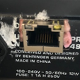
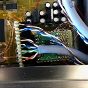
DCX2496 has a digital input as standard, so what I need is just to add 2 band digital outputs. I did not cut or replace existing components but just soldered 8 wires to the main board, except a RJ45 connector hole between AC input and RS-232C connector.
sorry for ugly finish
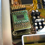
Soldering wires to the main board
I have connected 8 wires to the main board, 2 out of 8 wires are not used at this moment, but future use. Red arrow shows 1 thrugh 6, and 7&8 are on the other side of the circuit board.
- Low Freq. Data: R54 (IC4 side) or pin 6 of IC4
- Mid Freq. Data: R55 (IC5 side) or pin 6 of IC5
- High Freq. Data: R56 (optional, IC6 side) or pin 6 of IC6
- ACLK12: pin 3 of IC4* (optional)
- BCLK: pin5 of IC5*
- LRCLK: pin7 of IC6*
- GND: pin 2 of IC7 or IC9 (5V regulator) from bottom side of the board
- Power: pin 1 of IC7 or IC9 (5V regulator) from bottom side of the board
*can be connected to any of IC4, IC5, IC6
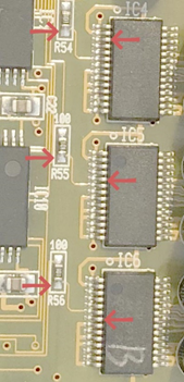
IC4, 5, 6 are AK4393 D/A converters with 28 pins, 0.65mm pitch. When connecting to IC4, 5, or 6, cover up adjacent pins with Kapton tape and solder a wire. Kapton tape is not necessarily removed and leave as is. The tape may reduce the chance to bridge solder to the next pin. I carefully soldered 2UEW 0.29mm wire. Soldering wires to R54, R55, R56 also needs attention because too much heat may move those registers.
Circuit
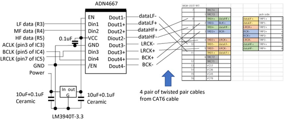
All wires are connected to a small daughter board with 3.3V regulator and a connector to grand-daughter board. Daughter board also has 5V regulator, and connection to HF data, as well as ACLK for future use, and attached to the housing via a screw through daughter-board - 10mm spacer – main-board. The grand-daughter board sits on the daughter borad's connector and has a LVDS driver (ADN4667) and a connector for output.
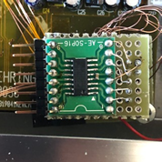
The output is LVDS level, via a 1000 Base-T RJ-45 (0838-1X1T-W7) connector. It has 4 isolation transformers built in and impedance is well controlled to 110ohm when used with CAT6 cable. Note that system clock (ACK from Pin3 of IC3, 4, or 5) is not connected to the output, because there is no vacant line, and Sample Rate Converter SRC4193 or SRC4192 does not require system clock from I2S source.
I have assigned High frequency to MF of DCX2496, so MF output is renamed to dataHF+/- at output side of ADN4667.
The connection of 1000baseT is based on Accuphase’s HS-LINK, where KEY is replaced with dataHF+/-.
(Optional)
Those who need 2 or 3 band SPDIF output, you can use one DIT4192 per band clocked with ACLK signal. DIT4192 ‘s TX+(pin 18)/TX-(pin17) can be wired to each pair of RJ-45 connector via a 0.1uF capacitor and a 110ohm register connected serially and use an RJ-45 connector with isolation transformers. At the other end of CAT6 cable, you may use another RJ-45 connector with transformer to connect XLR connectors (AES/EBU).
As of Feb 18 2021, modification is done, but have never been tested yet.
DCX2496の改造は、アナログ回路や電源を改善するものや、帯域ごとにSPDIF出力を追加するものがあるようです。
DCX2496は標準でデジタル入力が可能なので、2バンドのデジタル出力を追加することにしました。改造は、回路を切ったり部品を取り替えたりはせず、電線をはんだ付けすることと、RJ-45の穴を電源とRS-232Cコネクターに取り付けるだけにしました。
メインボードへの電線の取り付け
下記のように、8本の電線をメインボードにはんだ付けしました。8本中、2本は将来のためで、現状は使っていません。
- 低域データ: R54 (IC4側) または、IC4の6ピン
- 中域データ: R55 (IC5側) または、IC5の6ピン
- 高域 Data: R56 (予備, IC6側) または、IC6の6ピン
- ACLK12: pin 3 of IC4* (予備)
- BCLK: pin5 of IC5*
- LRCLK: pin7 of IC6*
- GND: pin 2 of IC7 or IC9 (5V レギュレータ) 基板の裏面に接続
- 電源: pin 1 of IC7 or IC9 (5V regulator) 基板の裏面に接続
* IC4, IC5, IC6の何れでも可
IC4, 5, 6 は AK4393 D/A コンバータで0.65mm間隔の28ピンです。電線を接続する際は、ハンダブリッジを予防するために、隣の両側のピンをカプトンテープで覆ってから、2UEW 0.29mmをはんだ付けしました。カプトンテープは貼ったままで大丈夫です。R54, R55, R56にハンダ付けする際、加熱しすぎると抵抗がずれてしまうので要注意です。
3.3Vのレギュレータとコネクタを載せたドーターボードに全ての電線を接続します。予備で5.0Vのレギュレータも搭載し、高域データとACLKも接続しています。ドーターボードは、スペーサーとメインボードを介して本体にネジ止めしました。孫ボードには、孫ボートはLVDSドライバADN4667と、出力コネクタを搭載しています。
高域の出力が必要な場合や、SPDIF出力が必要になったときなど、孫ボードを作り変えることができます。
出力はLVDS信号で、1000 Base-T RJ-45 (0838-1X1T-W7)コネクタに出力します。このこねくたには、アイソレーショントランスが搭載され、CAT6ケーブルを使えば、インピーダンスも正確に110Ωに合わせられます。なお、出力コネクタに空きがないため、システムクロック(ACK)は出力されません。サンプルレートコンバーターの SRC4193 or SRC4192 を使えば、I2Sの信号源にはクロックは必要無いためです。DCX2496は、中域に高音を設定しているので、中域の信号は、ADN4667の出力側以降はdataHF+/-としています。
1000BaseTの接続はアキュフェースのHS-LINKを参考に、KEYをdataHF+/-に差し替えています。
(おまけ)
2~3バンドのSPDIFが必要な向きには、バンドごとに、DIT4192を使うことができます。クロックはACLKからとり、DIT4192のTX+(pin 18)/TX-(pin17) を、0.1μFと110Ωをシリーズ接続してRJ-45 に接続できます。CAT6ケーブルの終端には、同様にトランス付きのRJ-45コネクター経由でXLR(AES/EBU)に接続することができます。
2021年2月18日現在、改造は済んでいますが、まだテストできていません。
Behringer DCX2496 Project
I start working on Behringer DCX2496 project and I decide to post my experience for future.
I have a very old pair of Martin Logan Ascent speakers. They are old but still makes great sound except that electro-static unit above 280Hz loosing sound level gradually, while low frequency unit is just fine.
It is possible to fix it by replacing electro-static panel or wash the panel; experienced Martin Logan user washes it.
but it seemed extremely hard to back it work again for me.
My simple solution was so-called bi-amplifier. I make up a barrack pre amplifier with 2 output per channel with gain adjustment for each. I added Sony TAN-330ES for Low frequency to a Mark Levinson No.331. I used white-noise source and free spectrum analyzer to adjust level of each cannel. In addition to adjust Low/High frequencies, Left/Light level required to be adjusted.
I could feel obvious improvement and had enjoyed the configuration without trouble for a while.
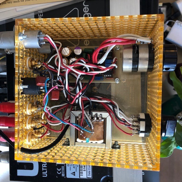
Picture: 3 input, 2 output with gain control preamplifier
The bad things are, its completeness as you can see, and the complex analog circuit that is substantially degrades sound quality. In addtion to that, the sound somewhat fuzzy by unknown reason.
Last year(2020), I added Behringer UltraDrive Pro DCX2496 speaker management system as an improvement project. I have adjusted DCX2496 with software tools provided, measurement microphone, and free spectrum analyzer. There is obvious improvement over bi-amp configuration, fuzzy sound gets some improvement.
However, I noticed that DCX2496 lacked output fader. I was expecting that I could have connected digital source directly to DCX2496 digital input. But, lack of fader means there is no method to control output level. If there were 4 channel balanced fader available, I could just get and connect fader between DCX2496 and power amplifiers.
Thus, analog output of digital source is connected to barrack preamplifier just for level control, then A/D converted in DCX2496. The barrack preamplifier still sits there just for level control.
Thus, I started this project for:
1. skip unnecessary DA/AD conversions,
2. simplify analog signal path,
3. skip DCX2469's analog circuit, said to be noisy.
The goals are:
1. DCX2496's modification to digital output,
2. To simplify analog signal path,
3. To learn how to use PIC (or RaspberryPi pico)
The plan includes:
1. multiple digital (SPDIF, I2S) inputs and capability to select source,
2. modification of DCX2496 to I2S outputs,
3. 2 of I2S input 2 channel Digital to Analog converter + power amplifier with fader,
4. (optional) analog inputs for tuner or other analog output devices,
5. use of PIC or RaspberryPi pico to control the system,
6. (optional) remote control.
as of Feb/17/2021, the project is under way.
ベリンガー DCX2496のプロジェクトをはじめたので、忘備録として記録します。
随分古いマーチンローガンのアセント(Ascent)を使っています。音はいいのですが、古くなるに従って、280Hz より上のコンデンサースピーカーの音が小さくなってきました。ユニットを交換するか、スピーカーユニットを外して洗うなどすればよいのですが、復旧できる自信はありません。
そこで、バイアンプを導入することにしました。
チャンネルごとに、2組のゲインを調整できるアンプを組み上げ、マークレビンソンのNo.331に加えて、低音用にソニーのTAN-330ESを追加しました。
ホワイトノイズと無料のスペクトルアナライザーを使い、低音/高音のレベルを調整しました。左右のレベルも差があったので、併せて調整しました。
結果、目論見通りの結果で、トラブルもなく、そのまま暫く使っていました。
ところが、原因はわからないのですが、音もなんとなくハッキリしないのが気になるようになりました。
昨年(2020), ベリンガーのUltraDrive Pro DCX2496スピーカーマネジメントシステムを追加することにしました。ベリンガーのソフトとマイク、フリーのスペクトルアナライザーで調整しました。バイアンプに比べるとだいぶ良く、音もクリアになりました。
ところが、DCX2496にはボリュームが付いていないことに気が付きました。デジタルの機器から直接DCX2496のデジタル入力に接続できると考えていたのですが、音量調節ができません。DCX2496とパワーアンプの間にボリュームを入れられればよかったのですが、バランス接続の4チャンネルのフェーダーなんてありません。
やむを得ず、音量調節のためだけに、デジタルの機器のアナログ出力とDCX2496のアナログ入力の間に挟む形になりました。
そこで、無駄なDA/AD変換をスキップし、アナログの信号パスを整理し、雑音が多いと言われているDCX2496のアナログ回路もスキップするために、このプロジェクトをはじめました。
目標は、DCX2496のデジタル出力改造、アナログ信号パスの簡素化と、PICの学習です。
計画では、なんチャンネルかのディジタル入力(SPDIF, I2S)の切り替え、DCX2496のI2S出力化、2チャンネルのI2S入力のボリューム付きDAC+パワーアンプ、チューナー用のADC(おまけ)、システムを制御するためのPIC(またはRaspberryPi pico)、できればリモコンもつけたいと思っています。
2021年2月17日現在、進行中です。
Quasi-Higi end from China
I recently a vacuum-tube power amplifier from Yahoo! Auctions in Japan. The spec is obviously high-end one, Yaquin MS-88B, KT88 pp 70W/ch.
It was definitely cheap, but it came with one cracked tube out of 10.
I wrote to them that I had problem, along with clear picture for a week ago. There is no response yet.
China is great, but it may be very far a way that light-speed e-mail takes more than a week.
OOMSAP, another story
Another pair of Quad was on an auction site, now sitting in the middle of old ones. That is listed as ESL-63Pro Junk, because one of them makes bussing sound, which makes bussing sound as explained.
One ESL-63Pro is now located at the middle of ESL-57 pair through channel mixer and 6dB/Oct LPF at 200Hz. AWCS only works below 50Hz (12dB/Oct @ 50Hz). I tried to adjust each level and crossover frequency without any test equipment, and that was so far successful.
I borrowed measurement microphone with a microphone preamplifier and 24bit/192KHz ADC.
The measurement result is unusual. The response is +3dB@100Hz, +5db@63Hz, and +5dB at 16Hz. That is practically flat. However, it is flat up to 16Hz. Connecting the cannon shaped blower makes obvious difference even though I barely hear its sound by itself, except rattle sound from some furniture at very high volume (but yet barely heard). The OOMSAP does not know the reason why the air vibration far below the audible frequency because OOMSAP is stupid.